

Honest, Unambiguous
and
Updated
technical information for Stevia Industries

Farming

Extraction

Formulation


Membrane Based Steviol Glycoside Purification Technology
Use of ion exchange resins, chemical flocculating and chelating agents and solvents in the conventional extraction and purification process of steviol glycosides seemed as incompatible to its “natural” and “organic” image to a group of workers. To address these issues, the membrane filtration based extraction technology has been proposed.
The essential features of this technology are as follows –
-
Apart from water, no other solvent is used in the process
-
Steviol glycosides are purified only on the basis of physical filtration
Recently, this technology is often being promoted as the “Holy grail” of extraction processes. But, like all other process technologies, it has also its pros and cons. Here, I am trying to “demystify” the process through a simple process description and discussions about its advantages and drawbacks.

The Process in Brief

Choice of Filters
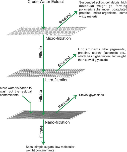
Membrane based steviol glycoside separation process is actually a combination of filtration process through filter media of different pore size. Each filtration stage requires very specific filter media with specific pore size range. Careful selection of filtration device is very essential for the success of the process. Let us have a look at the required parameters and options available for all the unit filtration processes.

Micro-filtration
Microfiltration usually serves as a pre-treatment for downstream separation processes such as ultrafiltration, and a post-treatment for filtration by filter press. The typical particle size used for microfiltration ranges from about 0.1 to 10 µm. In terms of approximate molecular weight these membranes can separate macromolecules of molecular weights generally less than 100,000 g/mol. The filters used in the microfiltration process are specially designed to trap particles such as – suspended solids, cell debris, high molecular weight gell forming polymeric substances, micro-organisms and some waxy materials. All the dissolved organic and inorganic components, small colloids, viruses and water pass through this filter.
There are two types of filter media for microfiltration, viz.


Screen filters - Particles and matter which are of the same size or larger than the screen openings are retained by the process and are collected on the surface of the screen. When new, media resistance of flow is small, but as the filter builds up with contaminants, the resistance to flow rapidly increases.
Depth filters - Matter and particles are embedded within the constrictions within the filter media, the filter surface contains larger particles, smaller particles are captured in a narrower and deeper section of the filter media. Normally, these filters have large holding capacities and initially have a higher resistance to flow.
Ultrafiltration and Nanofiltration
Both the ultrafiltration and nanofiltration processes involve filtration with special membranes which traps particles with a specific molecular weight range. Ultrafiltration can trap particles as small as 0.01 micron diameter and nanofiltration can trap particles as small as 0.001 micron diameter. Molecular weight cut-off (MWCO) is a method of characterization used in filtration to describe pore size distribution and retention capabilities of ultra- and nano-filtration membranes. It is defined as the lowest molecular weight (in Daltons) at which greater than 90% of a solute with a known molecular weight is retained by the membrane. Membranes with MWCO 1,000 - 100,000 Daltons are termed as Ultrafiltration membranes and that with MWCO 100 – 1,000 Daltons are termed as Nanofiltration membranes. Considerable pressure differential is required to push the fluids through these membranes. For ultrafiltration the required pressure differential is 2 – 10 bars and for Nanofiltration, it is 5 – 30 bars.
"Dead End" or "Cross Flow"
Dead End Filtration
The most basic form of filtration is Dead-End filtration. In Dead-End filtration, the aqueous extract is forced through the filter surface by applied pressure. Retained particles stay behind on the filter surface while filtered extract flows through. The retained particles accumulate on the filter surface and consequently, the filtered extract experiences a greater resistance to passing through the filter. This may result in a decrease in flow rate.
In Dead End filtration, since the removed solids accumulate on the surface of the filter, filters and/or screens require cleaning to restore performance. For this reason, modern large filtration devices have self cleaning screens. In this type of filtration, two streams are generated - the feed (crude extract going through the filter or screen) and permeate (the filtered extract passing through the filter media).
Cross Flow Filtration
Cross-flow filtration (also known as tangential-flow filtration) is a filtration technique in which the crude extract passes along the surface of the membrane. The constant turbulent flow along the membrane surface prevents the accumulation of matter on the membrane surface. A pressure difference across the filtering media drives extract through the membrane (permeate) while particles that are retained (retentate) by the membrane continue to pass along the membrane surface. The process is referred to as “cross-flow” because the crude extract flow (and retentate) flow(s) and permeate flow are perpendicular (90°) to one another.
Whereas dead-end flow has two streams, cross-flow filtration has three streams: feed (crude extract entering into the filtratiuon device, permeate (filtered extract) and retentate (extract with retained particles). Cross-flow filtration is an excellent way to filter extracts with a high concentration of filterable matter. The feed and concentrate flows help keep the membrane surface clean and free of accumulated matter so the membrane may continue to perform with less frequent cleanings.
In cross-flow filtration, it is important to maintain a high cross-flow velocity (or concentrate flow) to keep the membrane surface free of accumulated matter.
Membrane fouling characteristics of dead end and cross flow filtration, as evaluated by time vs flow rate relation.

Filtration Membrane Geometries
Industrial filtration systems generally use four types of filter membrane geometries. The adopted geometries are application and process parameter specific.

Spiral Wound Configuration
Spiral-wound configuration consist of membranes, feed spacers, permeate spacers, and a permeate tube. First, a membrane is laid out and folded in half with the membrane facing inward. Feed spacer is then put in between the folded membranes, forming a membrane sandwich. The purpose of the feed spacer is to provide space for water to flow between the membrane surfaces, and to allow for uniform flow between the membrane leaves. Next, the permeate spacer is attached to the permeate tube, and the membrane sandwich prepared earlier is attached to the permeate spacer using glue. The next permeate layer is laid down and sealed with glue, and the whole process is repeated until all of the required permeate spacers have been attached to the membranes. The finished membrane layers then are wrapped around the tube creating the spiral shape.
Feed travels through the flow channels tangentially across the length of the element. Filtrate will then pass across the membrane surface into the permeate spacer, where it is carried down the permeate spacer towards the permeate tube. The feed then becomes concentrated at the end of the element body. Spiral-wound elements come in multiple configurations with different spacers, membrane types, lengths, and diameters that allow it to fit multiple applications. These elements have a very high packing density, surpassing the packing density of plate and frame, tubular, and capillary configurations. Spiral membranes allow for easy cleaning through cleaning in place and backwash.

Tubular membranes
Tubular membrane modules are tube-like structures with porous walls. Tubular modules work through tangential cross-flow, and are generally used to process difficult feed streams such as those with high dissolved solids, high suspended solids, and/or oil, grease, or fats.
Tubular modules consist of a minimum of two tubes; the inner tube, called the membrane tube, and the outer tube, which is the shell. The feed stream goes across the length of the outer tube and is filtered in into the inner tube while concentrate collects at the opposite end of theOuter tube. Low packing density and large size are disadvantages of tubular modules. Packing density of tubular modules is higher than plate and frame systems but lower than capillary, hollow fiber, and spiral wound elements. Because of the large inner diameter of the tubular modules, flow requirements are higher than those of other system configurations.
Tubular systems have less fouling compared to plate and frame systems, and a similar amount of fouling when compared to spiral and capillary. Tubular systems allow for robust cleaning methods such as the use of harsh chemicals, backwash, and even mechanical cleaning which might not be available for other system configurations.

Hollow Fiber Membranes
Hollow fiber filtration utilizes numerous long porous tubes or hollow fibers packed inside an outer shell. Each filament is very narrow in diameter and very flexible. Hollow fiber filtration works on the same principle as tubular, but utilizes a small tube diameter which allows for flexibility and high total filtering surface area. Permeate flux in hollow fiber filter systems are much higher than that of tubular systems.
Irreversible fouling and easy breakage are the main problems concerning hollow fiber filtration. Because of the flexibility of the fibers, they are more likely to break when under high strain compared to other methods of filtration such as tubular or spiral wound elements.
Plate and Frame Membranes
Plate and Frame membrane systems utilize membranes laid on top of a plate-like structure, which in turn is held together by a frame-like support. For cross flow plate and frame membrane systems, fouling of the membrane is significantly less because the flow is tangential and does not require use of the cake filtration system. It works on the basic principles of cross flow where feed enters on one side of the plated membrane and retentate collects on the other end of the plate. Permeate travels through the membrane and collects on the inside of the supporting plate. Easy separation of solids from extracts and easy removal/cleaning of filter surfaces are the main advantages of plate and frame membrane systems.
Low total filtering surface area is one major problem for plate and frame membrane systems. Low efficiency compared to other configurations, and high pressure drop, are other problems that plague plate and frame systems as well.

R & D Chronicle for Purification of Steviol Glycosides Through Membrane Filtration
Process Engineering Considerations
Study of all the R&D work done so far indicates that, in all the filtering stages, adoption of cross flow filtration system is preferable.
For micro-filtration, filter cartridges in tubular or spiral wound configuration may be used. For micro filtration application, the filtering medium can be nylon. Cellulose acetate or polyether sulphone.
For ultra-filtration and nano-filtration stages, spiral wound or hollow fiber configuration should be ideal. For ultrafiltration, the membranes may be made of cellulose acetate, polysulfone, Polyether sulfone, Polyacrilonitrile, Polyvinylidiene fluoride, Polypropylene, Polyethylene or Polyvinyl chloride. Polyamide thin film composites are the most preferred material for nano-filtration membranes.
The cross flow filtration systems are generally fabricated as standalone skids with integral high pressure pump, filter column array, feed, retentate and permeate manifold and valves for forward filtration and backwash. The following schematic represents the basic construction of a cross flow filtration system.


Claimed advantages of the process
Drawbacks of the process

1. Low selectivity of the process :
The molecular weight range of steviol glycosides overlap with that of many other contaminants. Many sugars and oligo-saccharides, polypeptides, tannins, photo-synthetic pigments, pesticides and other organic molecules have molecular weight range similar to steviol glycosides. These contaminants cannot be separated from steviol glycosides only by filtration based on difference in molecular weight and size.
2. Inverse relationship between yield and quality
There is always an antagonistic relationship between process yield and product quality. For the same membrane, if transmembrane pressure is increased to increase flux, the selectivity of the membrane decreases. For this reason, to maintain the selectivity of the filtration device, low transmembrane pressure needs to be used. Thus, acceptable purity level is always linked to sub-optimal process yield.
3. Concentration polarization
Filtration through membrane results into deposition of solute particles on the membrane surface. Thus, the concentration of solute on the membrane surface becomes more than that of the bulk feed solution and a gradient in solute concentration in the thin boundary layer forms. This phenomena is known as “concentration polarization”. Concentration polarization affects the membrane performance in many ways –
-
High concentration of solutes near the membrane exerts an osmotic pressure, which hinders free diffusion of solutes through the membrane from the feed side to the permeate side.
-
Formation of a poorly permeable solute layer on the membrane and resultant decrease in flux.
-
Adsorption of solute molecules on the internal surface of the pores, thereby decreasing the effective pore size and the permeability.
4. Membrane fouling
It is a process whereby a solution or a particle is deposited on a membrane surface or in membrane pores, so that the membrane's performance is degraded. It is a major obstacle to the widespread use of this technology. Membrane fouling can cause severe flux decline and affect the quality of the permeate. Severe fouling may require intense chemical cleaning or membrane replacement. There are various types of foulants: colloidal (clays, flocs), biological (bacteria, fungi), organic (oils, polyelectrolytes, humics) and scaling (mineral precipitates).
Fouling can be divided into reversible and irreversible fouling based on the attachment strength of particles to the membrane surface. Reversible fouling can be removed by a strong shear force or backwashing. Formation of a strong matrix of fouling layer with the solute during a continuous filtration process will result in reversible fouling being transformed into an irreversible fouling layer. Irreversible fouling is the strong attachment of particles which cannot be removed by physical cleaning.
5. Low recovery and purity
The recovery percentage of steviol glycoside in membrane separation process is much lower than the conventional processes and the end product purity level is also low. Individual glycosides can not be separated by membrane process alone, thus, purification upto Reb A 98% level is not possible.
Conclusion
In the present technology scenario, membrane filtration, alone, may not be sufficient in achieving commercially viable recovery percentage and acceptable purity level.
Membrane filtration may be used within the conventional processes to concentrate the aqueous extract, and the concentrated extract may be subsequently processed through the conventional resin process or liquid-liquid solvent extraction process. This may help in decreasing the material handling and downsizing the equipment for resin process or liquid-liquid solvent extraction process.
The economic feasibility of industrial scale integration of membrane filtration and conventional technologies can only be figured out through comparison of additional infrastructural cost for membrane filtration system vis a vis infrastructural cost saving due to downsizing of downstream process equipment. Specifically, in the liquid-liquid solvent extraction process (Resin Free Process), integration of membrane filtration stages to concentrate aqueous extract may reduce the energy cost and overall process cost to some extent.